E-mail: hedy@chbns.com
 English


Scope of use
● Do not use this inverter in equipment that may threaten life or harm the human body due to inverter failure or work error (nuclear power control equipment, aerospace equipment, vehicle equipment, life support systems, safety equipment, weapon systems, etc.). For special purposes, please consult our company in advance.
● This product is manufactured under the supervision of strict quality management system, but when used for important equipment, there must be safety protection measures to prevent the inverter failure to expand the scope of the accident
Installation Environment
●Installed indoors, in a well-ventilated place, generally should be installed vertically to ensure the best cooling effect. For horizontal installations, additional ventilation may be required.
●The ambient temperature is required to be within the range of -10 to 40°C. If the temperature exceeds 40°C, please remove the upper cover. If the temperature exceeds 50°C, external heat dissipation or derating is required. It is recommended that users do not use the inverter in such a high temperature environment, because it will greatly reduce the service life of the inverter.
●The ambient humidity is lower than 90%, and no condensation occurs.
●Install in a place with vibration less than 0.5G to prevent falling damage. The inverter is not allowed to suffer from sudden impact.
●Install in an environment far away from electromagnetic fields and without flammable and explosive substances.
Technical Specification
Input | Rated Voltage,Freq uency | 3-phase AC380V;50/60H 1-phase AC220V;50/60Hz | |
Allowed Voltage Range | 3-phase AC360V~450V 1-phase AC190V~250V | ||
Out put | Voltage | 0~460V 0~260V | |
Frequency | Low frequency mode:0~300H High frequency mode:0~3000Hz | ||
Overload Capacity | G Type:110% for long-term, 150% for 1 min 200% for 4 P Type:105% for long-term 120% for 1 min 150% for 1s | ||
Control Mode | V/F control、Advanced V/F control、V/F separation control,、No PG current vector control | ||
Control Character | Frequency | Analog Input | 0.1% of maximum output frequency |
Digital Setting | 0.01Hz | ||
Frequency | Analog Input | Within 0.2% of maximum output frequency | |
Digital Setting | Within 0.01% of set output frequency | ||
V/F Control | V/F Curve (voltage | Reference frequency can be set arbitrarily from 0.5 to 3000Hz, multi-point V/F curve can be set arbitrarily, and various fixed curves such as constant torque, reduced torque 1, reduced torque 2, and square torque can also be selected | |
torque boost | Manual setting: 0.0~30% of rated output Automatic boost: automatically determine the boost torque according to the output current and combined with the motor parameters | ||
Automatic Current-limiting and | During acceleration, deceleration or steady running, detect automatically the current and voltage of motor stator, and control it within boundsbased on unique algorithm, minimize fault-trip chance | ||
Control Character | Senseless Vector Control | Voltage Frequency | Adjust pressure/frequency ratio according to motor parameter and unique algorithm |
Torque Character | Starting torque: 3.0Hz 150% rated torque (VF control) | ||
Motor Parameter Self-measurement | Without any restrictions, the automatic detection of parameters can be completed under the static and dynamic conditions of the motor to obtain the best control effect | ||
Current and | Current closed-loop control, free from current impact, perfect restrain function of overcurrent and overvoltage | ||
Undervoltage Restrain during Running | Specially for users with a low or unsteady voltage power grid: even lower than the allowable voltage range, the system can maintain the longest possible operating time based on its unique algorithm and residual energy allocation strategy | ||
Typical Function | Multi-speed and swing frequency operation | 16 segments programmable multi-segment speed control, a variety of operating modes are optional. Swing frequency operation: preset frequency, center | |
PID Control RS485 Communicati on | Built-in PID controller (able to preset frequency). Standard configuration RS485 communication function, multiple communication protocol for choice, synchronizing control function. | ||
Frequency Setting | Analog Input | DC voltage 0~10V, DC current 0~20mA (upper and lower limit optional) | |
Digital Input | Operation panel setting, RS485 interface setting, UP/DW terminal control, and various combination setting with analog input | ||
Output Signal | Digital Output | 2-channel Y terminal open collector output and | |
Analog Output | 2-channel of analog signal output, the output range can be flexibly set between 0~20mA or 0~10V, which can realize the output of physical quantities such as set frequency and output frequency | ||
Automatic Steady | Dynamic steady state, static steady state, and unsteady voltage for choices to obtain the steadiest operation | ||
Acceleration and Deceleration Time Setting | 0.1s~3600.0min continuous setting, S type and linear type mode for choice | ||
Braki ng | Dynami c braking | Dynamic braking initial voltage, backlash voltage and dynamic braking continuous adjustable | |
DC Braking | Halt DC braking initial frequency:0.00~【F00.13】upper limit frequency Braking time: 0.0~100.0s; Braking current: 0.0%~150.0% of rated current | ||
Flux Braking | 0~100 0:invalid | ||
Low Noise Running | Carrier frequency 1.0kHz~16.0kHz continuous adjustable, minimize motor noise | ||
Speed Tracking and Restart Function | Smooth restart during operation, instantaneous stop and restart | ||
Counter | A built-in counter, facilitate system integration | ||
Operation Function | Upper limit and lower limit frequency setting, frequency hopping operation, reversal running restraint, slip frequency compensation, RS485 communication, frequency control of progressive increase and decrease, failure recovery aomatically, etc. | ||
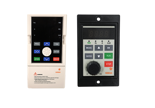
Display | Oper ation Panel Display | Running State | Output frequency, output current, output voltage, motor speed, set frequency, module temperature, PID setting, feedback, analog input and output, etc. |
Alarm | The latest 6 faults record; records 6 operating parameters such as output frequency, set frequency, output current, output voltage, DC voltage, and module temperature when the latest fault tripped | ||
Protective Function | Overcurrent, overvoltage, undervoltage, module fault, electric thermal relay, overheat, short circuit, default phase of input and output, motor parameter adjustment abnormality, internal memory fault, etc. | ||
Environment | Ambient Temperature | -10°C ~ +40°C (please run the VFD in derated capacity when ambient temperature is 40°C~50°C) | |
Ambient Humidity | 5%~95%RH,no condensation | ||
Surroundings | Indoors (without direct sunlight, corrosive or flammable gas, oil fog and dust) | ||
Altitude | Running in derated capacity above 1000m, derate 10% for every 1000m rise | ||
Structure | Protection Level | IP20 | |
Cooling Method | Air cooling with fan control | ||
Installation Method | Wall-hanging type, cabinet type | ||
Frequency Converter